Patent pending. Application # PCT/IB2021/056658 – WO/2023/002238
State of Art
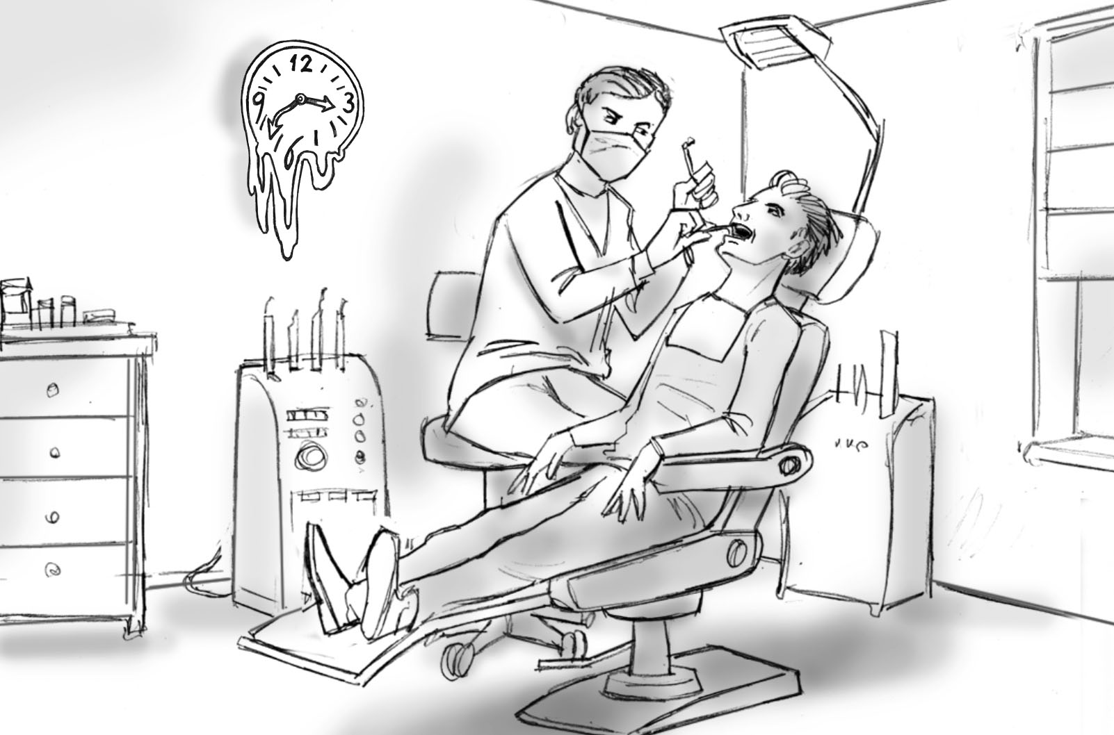
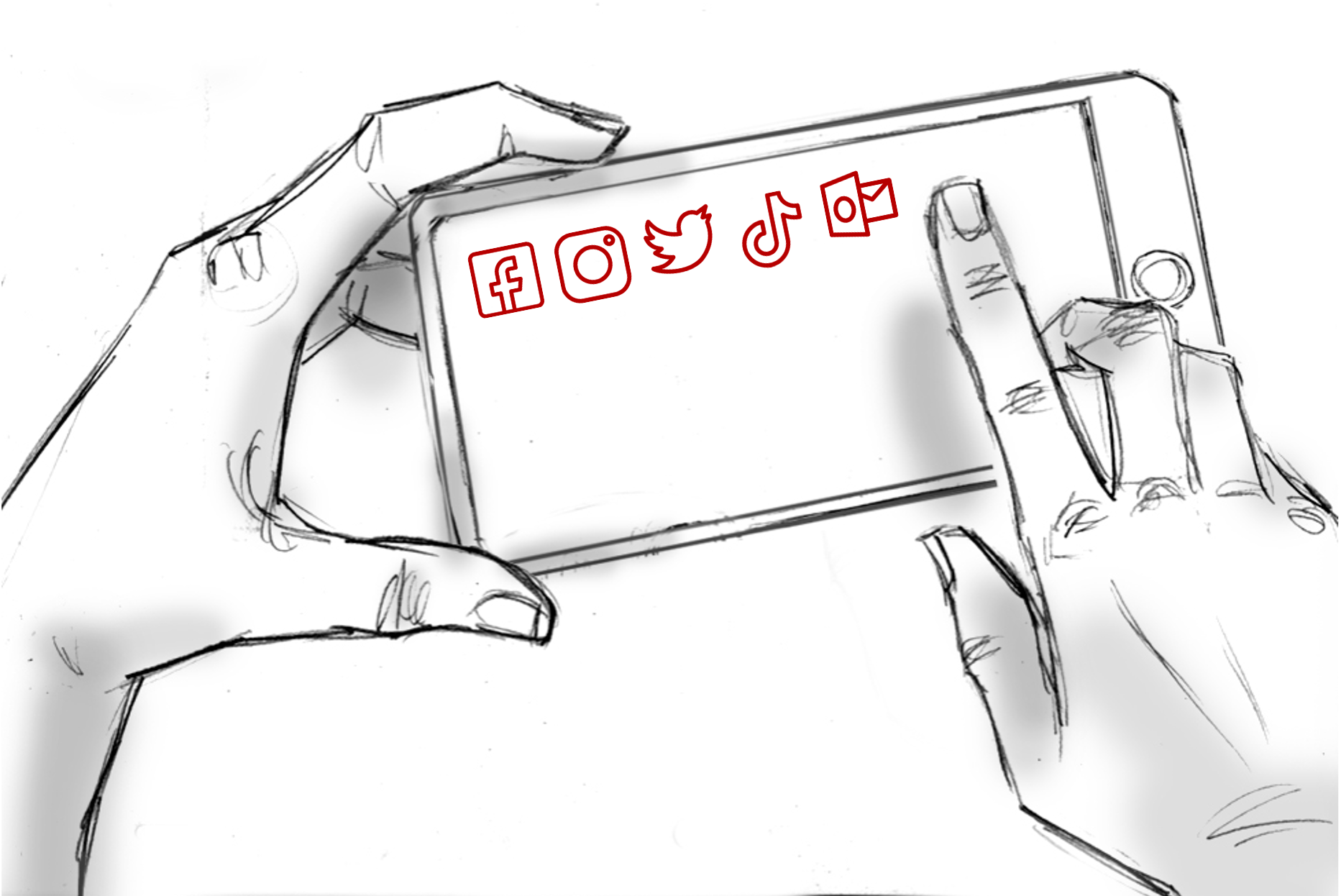
A smartphone is an integral part of major people’s lives. People use it for work, entertainment, communication, information reception or just to “kill time”. It becomes a habit to constantly have a phone “at hand”, or rather, to always be able to see information on its screen and use it. This habit usually occurs in situations when a person has more free time. In most cases, the phone is accessible to a person, however there are circumstances or situations when it is very complicated or even impossible to use the phone. For example, during a visit to the dentist. When a dentist examines or treats a patient, the latter usually does not have access to the phone, since various dental equipment and tools, as well as the staff interfere with the direct vision of phone screen (in the case of smartphones – they can usually be applied by touching the screen with the fingers and with a need to see both the screen and one’s fingers). The ability to use a smartphone during dental treatment or other procedures would allow the patient to make effective use of his/her time, and the shift in focus from the treated area of the body to the contents of the phone will make the patient experience easier.

The technical solution described in the Patent application # PCT/IB2021/056658 characterized in that a smart device (e.g. smartphone) is placed next to a holder equipped with camera coupled with a device mounted in front of the user’s eyes, in the screen therein (e.g. in VR glasses) the user can see a real image of his/her smart device screen (e.g. smartphone) as well as his/her fingers operating such smart device. Thereby the user can use his/her smart device (e.g. smartphone) as usual, i.e. viewing his/her fingers and the device screen, and, contrary to the closest patent document, the real images of the smart device screen and user’s fingers are displayed; the smart device screen rendered / overlaid by monochromatic screen is not required for detection of finger position, and the detection of physical objects between the head mounted device and smart device is not needed. Also, no additional training is required in the use of user interfaces and the control system of virtual reality glasses or other similar devices, and there is no need to install additional software on a smart device. In addition, the system described in the disclosure ensures the privacy of the smart device user since no additional software is required, and with addition of protective element, such as a hood, unauthorized persons cannot see the contents of the user’s smart device screen. Furthermore, the system is of closed type as it does not record or transmit the image (including screen content) of the user’s smart device to others, although it can do so if necessary. The described solution also allows using other tools that are out of direct vision of the user, for example, reading a book, taking notes, drawing sketches, etc.
Claims
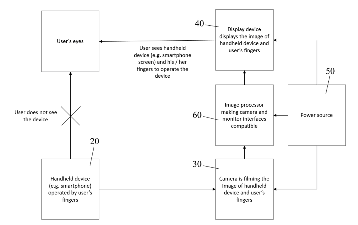
1. System for manual control of a device that is out of user’s direct vision, characterized in that the above system comprises:
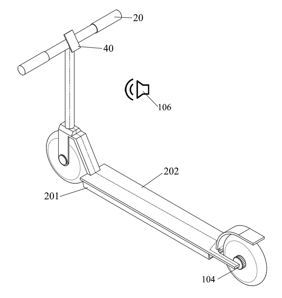
– a holder (10) where at least one video camera attached to (30),
– a handheld device (20), placed next to (under) camera (30),
– a display device (40), coupled with video camera (30), to display the image of the handheld device (20) (in the case of a smartphone – its screen and the image of the position of user’s fingers operating the smartphone),
– at least one image processor (60), connected between camera (30) and display device (40), and applied only when the compatibility of camera (30) and display device (40) interfaces is required,
– video camera (30) and/or processor (60) parameters are adjusted, when needed.
2. The system according to Claim 1, characterized in that further comprises at least one power source (50) to feed video camera (30), display device (40) and image processor (60).
3. The system according to any of the preceding claims, characterized in that further comprises a protective element (103) to cover the handheld device (20) and, if needed, video camera (30) from prying eyes and/or surveillance cameras or similar equipment, and/or physical impact.
4. The system according to Claim 3, characterized in that a protective element (103) is connected to the holder (10).
5. The system according to Claim 1, characterized in that the holder (10) can be installed or placed on various objects, and the holder’s (10) size is fixed by rigid joint, or adjustable by sliding joint.
6. The system according to any of the preceding claims, characterized in that further comprises a retaining element of handheld device (20) to secure the handheld device (20) in stable position subject to camera or for other purposes.
7. The system according to Claim 6, characterized in that a retaining element of handheld device (20) further comprises a hand and/or finger support to comfortably hold and/or operate the handheld device (20)
8. The system according to any of the preceding claims, characterized in that additionally comprises a holder’s (10) locking element to fix camera (30) to user’s hand or other part of the body, or other nearby object.
9. The system according to any of the preceding claims, characterized in that additionally comprises a switch integrated in the holder (10) or protective element (103) to turn on/off the video camera (30) and/or display device (40), and/or image processor (60), if the latter is applicable.
10. The system according to any of the preceding claims, characterized in that additionally comprises a control light to inform the user that video camera (30) is on and transmitting the image to the display device (40).
11. The system according to any of the preceding claims, characterized in that additionally comprises an adjustment device for camera (30) and/or image processor (60) settings.
12. The system according to any of the preceding claims, characterized in that the camera (30), display device (40) and image processor (60), when the latter is in use, are interconnected by physical connection or wireless connection.
13. The system according to Claim 2, characterized in that a power source (50) additionally comprises an indicator showing the charge level of the power source (50) and warning the user about the necessity of power source charging (50).
14. The system according to any of the preceding claims, characterized in that the handheld device (20) is a smartphone or tablet.